| Maximum operating pressure |
310 BAR (4500 PSI) |
| Rated flow capacity |
63 LPM (16.8 GPM) MAX – Varies by spool type |
| Maximum tank line back pressure |
138 BAR (2000 PSI) |
| Maximum frequencies of operation |
300 CPM |
| Recommended filtration |
25 MICRON |
| Hydraulic fluids |
Mineral Oil, Viscosity 10 – 400 cST |
| Temperature range |
-25° C to +90° C (-13° F to +194° F) |
Solenoid Ratings – top
| ELECTRIC SOURCE |
COIL TYPE |
VOLTAGE |
CURRENT & POWER |
|
|
| Hz |
SOURCE |
RANGE |
IN-RUSH |
HOLDING |
WATTAGE |
|
| RATED |
(±10%) |
CURRENT (A) |
CURRENT (A) |
|
|
| AC |
A24 |
60 |
AC24V |
21.6-26.4 |
6.8 |
1.7 |
|
|
| (-10 and -20 Options) |
A110 |
50 |
AC100V |
90-110 |
1.60 |
0.46 |
|
|
| |
60 |
AC100V |
90-110 |
1.40 |
0.32 |
|
|
| |
AC110V |
99-121 |
1.50 |
0.39 |
|
|
| |
A120 |
50 |
AC110V |
99-121 |
1.30 |
0.38 |
|
|
| |
60 |
AC120V |
108-132 |
1.20 |
0.27 |
|
|
| |
A220 |
50 |
AC200V |
180-220 |
0.80 |
0.23 |
|
|
| |
60 |
AC200V |
180-220 |
0.70 |
0.16 |
|
|
| |
AC220V |
198-242 |
0.75 |
0.19 |
|
|
| |
A240 |
50 |
AC220V |
198-242 |
0.67 |
0.1 9 |
|
|
| |
60 |
AC240V |
216-264 |
0.59 |
0.13 |
|
|
| R |
R110 |
50 |
AC100V |
90-110 |
0.30 |
0.30 |
26 |
|
| (-10 and -20 Options) |
60 |
AC110V |
99-121 |
0.30 |
0.30 |
|
| |
R220 |
50 |
AC200V |
180-220 |
0.15 |
0.15 |
|
| |
60 |
AC220V |
198-242 |
0.15 |
0.15 |
|
| |
R240 |
50 |
AC220V |
180-220 |
0.14 |
0.14 |
|
| |
60 |
AC240V |
216-264 |
0.14 |
0.14 |
|
| DC |
D12 |
DC 12V |
10.8-13.2 |
2.20 |
2.20 |
|
| (-10 and -20 Options) |
D24 |
DC 24V |
21.6-26.4 |
1.10 |
1.10 |
|
| DC |
D12 |
DC 12V |
10.8-13.2 |
2.60 |
2.60 |
28.8 |
|
| (-31 and -41 Options) |
D24 |
DC 24V |
21.6-26.4 |
1.30 |
1.30 |
|
TECHNICAL DATA: – top
• Solenoid can be used within -10% to +10% of the rated voltage of the coil.
• Withstand voltage 1500 v/sec.
• Insulation resistance over 100mQ
• Conforms to rating IP65
• A momentary signal of approx 0.1 second is required for shifting action.
ACCESSORIES: – top
• Mounting bolt kits are supplied with valve socket head cap screws
(#10-24UNCx1-3/4″L 4 pcs) for tightening torque 50-70 kgf-cm (43.3-60.6 lb-in).
• O-Ring AS568-012 4 pcs.
PRESSURE DROP AND PERFORMANCE CURVES – top
| TEST SYSTEMS
1. Testing Valve
2. Pump
3. Pressure Sensor
4. Flow Sensor
5. Relief Valve
6. Throttle Valve
TEST CONDITIONS
Pressure: 69 BAR (1000PSI)
Flow Rate: 63 LPM(16.8GPM)
Viscosity: 35 cSt (175SSU)
TEST CIRCUIT |
| PERFORMANCE CURVES |
|
CONTRAST CHART BETWEEN FACTORS AND VISCOSITIES
| VISCOSITY |
cSt |
15 |
20 |
30 |
40 |
50 |
60 |
70 |
80 |
90 |
100 |
| SSU |
77 |
98 |
141 |
186 |
232 |
278 |
324 |
371 |
417 |
464 |
| FACTOR (G) |
0.81 |
0.87 |
0.96 |
1.03 |
1.09 |
1.14 |
1.19 |
1.23 |
1.27 |
1.30 |
The pressure drop (AP’) can be obtained from the formula
AP’=AP (G’/0.85) for other specific gravity (G’). |
| MODEL |
PRESSURE DROP CURVE NUMBER |
| NO. |
P>A |
B>T |
P>B |
A>T |
P>T |
| C2 |
5 |
5 |
5 |
5 |
_ |
| C3 |
6 |
6 |
6 |
6 |
4 |
| C4 |
5 |
6 |
5 |
6 |
_ |
| C40 |
5 |
5 |
5 |
5 |
_ |
| C5 |
2 |
2 |
2 |
2 |
4 |
| C6 |
1 |
1 |
1 |
1 |
4 |
| C60 |
1 |
1 |
1 |
1 |
3 |
| C7 |
6 |
5 |
6 |
5 |
_ |
| C8 |
5 |
5 |
5 |
6 |
_ |
| C9 |
6 |
5 |
5 |
5 |
_ |
| D2 |
5 |
5 |
5 |
5 |
_ |
| D3 |
5 |
3 |
5 |
3 |
_ |
| B2 |
4 |
5 |
4 |
5 |
_ |
| B3 |
3 |
3 |
5 |
5 |
_ |
| B20 |
2 |
_ |
5 |
_ |
_ |
| B2S |
4 |
5 |
4 |
5 |
_ |
| B3S |
5 |
5 |
3 |
3 |
_ |
| B20S |
5 |
_ |
2 |
_ |
_ |
|
|
List of Spool Functions: – top
| THE MAXIMUM FLOW RATE LPM(GPM) UNDER DIFFERENT PRESSURE BAR (PSI) |
| SPOOL TYPE NORMAL POSITION |
|
| 50 BAR (735 PSI) |
100 BAR (1470 PSI) |
150 BAR (2200 PSI) |
207 BAR (3000 PSI) |
250 BAR (3675 PSI) |
310 BAR (4500 PSI) |
50 BAR (735 PSI) |
100 BAR (1470 PSI) |
| C2 |
63 (16.8) |
63 (16.8) |
63 (16.8) |
63 (16.8) |
63 (16.8) |
63 (16.8) |
40 (10.7) |
40 (10.7) |
| 32 (8.5) |
25 (6.7) |
| C3 |
63 (16.8) |
63 (16.8) |
63 (16.8) |
63 (16.8) |
63 (16.8) |
63 (16.8) |
63 (16.8) |
63 (16.8) |
| C4 |
63 (16.8) |
63 (16.8) |
63 (16.8) |
63 (16.8) |
63 (16.8) |
63 (16.8) |
40 (10.7) |
40 (10.7) |
| 32 (8.5) |
25 (6.7) |
| C40 |
63 (16.8) |
63 (16.8) |
63 (16.8) |
63 (16.8) |
63 (16.8) |
63 (16.8) |
40 (10.7) |
40 (10.7) |
| 32 (8.5) |
25 (6.7) |
| C5 |
50 (13.3) |
50 (13.3) |
50 (13.3) |
50 (13.3) |
50 (13.3) |
|
50 (13.3) |
50 (13.3) |
| C6 |
40 (10.7) |
40 (10.7) |
40 (10.7) |
40 (10.7) |
40 (10.7) |
|
40 (10.7) |
40 (10.7) |
| C7 |
63 (16.8) |
63 (16.8) |
63 (16.8) |
63 (16.8) |
63 (16.8) |
63 (16.8) |
40 (10.7) |
40 (10.7) |
| 32 (8.5) |
25 (6.7) |
| C8 |
63 (16.8) |
63 (16.8) |
63 (16.8) |
63 (16.8) |
63 (16.8) |
63 (16.8) |
40 (10.7) |
40 (10.7) |
| 32(8.5) |
25 (6.7) |
| C9 |
63 (16.8) |
63 (16.8) |
63 (16.8) |
63 (16.8) |
63 (16.8) |
63 (16.8) |
40 (10.7) |
40 (10.7) |
| 32 (8.5) |
25 (6.7) |
| B2 |
63 (16.8) |
63 (16.8) |
63 (16.8) |
63 (16.8) |
63 (16.8) |
63 (16.8) |
63 (16.8) |
20(5.3) |
| B3 |
63 (16.8) |
63 (16.8) |
63 (16.8) |
63 (16.8) |
63 (16.8) |
63 (16.8) |
63 (16.8) |
63 (16.8) |
| B20 |
|
|
|
|
|
|
35 (9.3) |
32 (8.5) |
| D2 |
63 (16.8) |
63 (16.8) |
63 (16.8) |
63 (16.8) |
63 (16.8) |
63 (16.8) |
40 (10.7) |
30 (8.0) |
| D3 |
63 (16.8) |
63 (16.8) |
63 (16.8) |
63 (16.8) |
63 (16.8) |
63 (16.8) |
40 (10.7) |
30 (8.0) |
|
| SPOOL TYPE NORMAL POSITION |
150 BAR (2200 PSI) |
207 BAR (3000 PSI) |
250 BAR (3675 PSI) |
310 BAR (4500 PSI) |
50 BAR (735 PSI) |
100 BAR (1470 PSI) |
150 BAR (2200 PSI) |
207 BAR (3000 PSI) |
250 BAR (3675 PSI) |
310 BAR (4500 PSI) |
| C2 |
18 (4.8) |
14 (3.7) |
10 (2.7) |
10 (2.7) |
40 (10.7) |
40 (10.7) |
18 (4.8) |
14 (3.7) |
10 (2.7) |
10 (2.7) |
| C3 |
12 (3.2) |
9.(2.4) |
7 (1.9) |
7 (1.9) |
32 (8.5) |
25 (6.7) |
12 (3.2) |
9.(2.4) |
7 (1.9) |
7(1.9) |
| C4 |
63 (16.8) |
63 (16.8) |
63 (16.8) |
63 (16.8) |
63 (16.8) |
63 (16.8) |
63 (16.8) |
63 (16.8) |
63 (16.8) |
63 (16.8) |
| C40 |
18 (4.8) |
14 (3.7) |
10 (2.7) |
10 (2.7) |
40 (10.7) |
40 (10.7) |
18 (4.8) |
14 (3.7) |
10 (2.7) |
10 (2.7) |
|
12 (3.2) |
9 (2.4) |
7 (1.9) |
7 (1.9) |
32 (8.5) |
25 (6.7) |
12 (3.2) |
9 (2.4) |
7 (1.9) |
7(1.9) |
| C5 |
18 (4.8) |
14 (3.7) |
10 (2.7) |
10 (2.7) |
40 (10.7) |
40 (10.7) |
18 (4.8) |
14 (3.7) |
10 (2.7) |
10 (2.7) |
|
12 (3.2) |
9 (2.4) |
7 (1.9) |
7 (1.9) |
32 (8.5) |
25 (6.7) |
12 (3.2) |
9 (2.4) |
7 (1.9) |
7(1.9) |
| C6 |
50 (13.3) |
50 (13.3) |
50 (13.3) |
– |
50 (13.3) |
50 (13.3) |
50 (13.3) |
50 (13.3) |
50 (13.3) |
– |
| C7 |
40 (10.7) |
40 (10.7) |
40 (10.7) |
– |
40 (10.7) |
40 (10.7) |
40 (10.7) |
40 (10.7) |
40 (10.7) |
– |
| C8 |
18 (4.8) |
14 (3.7) |
10 (2.7) |
10 (2.7) |
40 (10.7) |
40 (10.7) |
18 (4.8) |
14 (3.7) |
10 (2.7) |
10 (2.7) |
|
12 (3.2) |
9 (2.4) |
7 (1.9) |
7 (1.9) |
32 (8.5) |
25 (6.7) |
12 (3.2) |
9 (2.4) |
7 (1.9) |
7(1.9) |
| C9 |
18 (4.8) |
14 (3.7) |
10 (2.7) |
10 (2.7) |
40 (10.7) |
40 (10.7) |
18 (4.8) |
14 (3.7) |
10 (2.7) |
10 (2.7) |
| 12 (3.2) |
9 (2.4) |
7 (1.9) |
7 (1.9) |
32 (8.5) |
25 (6.7) |
12 (3.2) |
9 (2.4) |
7 (1.9) |
7(1.9) |
| B2 |
18 (4.8) |
14 (3.7) |
10 (2.7) |
10 (2.7) |
40 (10.7) |
40 (10.7) |
18 (4.8) |
14 (3.7) |
10 (2.7) |
10 (2.7) |
|
12 (3.2) |
9 (2.4) |
7 (1.9) |
7 (1.9) |
32 (8.5) |
25 (6.7) |
12 (3.2) |
9 (2.4) |
7 (1.9) |
7(1.9) |
| B3 |
20 (5.3) |
20 (5.3) |
20 (5.3) |
20 (5.3) |
63 (16.8) |
63 (16.8) |
63 (16.8) |
63 (16.8) |
63 (16.8) |
63 (16.8) |
| B20 |
63 (16.8) |
63 (16.8) |
63 (16.8) |
63 (16.8) |
63 (16.8) |
63 (16.8) |
63 (16.8) |
37 (9.9) |
30 (8.0) |
28 (7.5) |
|
45 (12.0) |
45 (12.0) |
45 (12.0) |
45 (12.0) |
45 (12.0) |
45 (12.0) |
| D2 |
25 (6.7) |
20 (5.3) |
18 (4.8) |
15 (4) |
63 (16.8) |
50 (13.3) |
45 (12.0) |
40 (10.7) |
32 (8.5) |
25 (6.7) |
|
45 (12.0) |
30 (8.0) |
28 (7.5) |
25 (6.7) |
22 (5.9) |
18 (4.8) |
| D3 |
25 (6.7) |
21 (5.6) |
16 (4.3) |
13 (3.5) |
40 (10.7) |
30 (8.0) |
25 (6.7) |
21 (5.6) |
16 (4.3) |
13 (3.5) |
|
25 (6.7) |
21 (5.6) |
16 (4.3) |
13 (3.5) |
40 (10.7) |
30 (8.0) |
25 (6.7) |
21 (5.6) |
16 (4.3) |
13 (3.5) |
NOTE:
1. The figures in the square show the flow under saturated temperature and 90% rated voltage.
2. The upper number in table describes the maximum flow under DC and R. the lower number in table describes the maximum flow under AC.
TEST SYSTEMS- top
1. Testing Valve
2. Pump
3. Pressure Sensor
4. Flow Sensor
5. Relief Valve
6. Throttle Valve
TEST CONDITIONS
Pressure: 138 BAR (2000PSI)
Flow Rate: 30 LPM(8 GPM)
Viscosity: 35 cSt(175 SSU)
TEST CIRCUIT
| MODEL |
CHANGE OVER TIME (sec) |
| T1 |
T2 |
| SWH-G02-AC SERIES |
0.01-0.04 |
0.02-0.04 |
| SWH-G02-DC SERIES |
0.02-0.06 |
0.02-0.04 |
OPTION LS- top
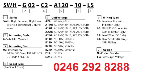
ELECTRICAL SURGE CONTROL MODEL SWH – G02 – *** – D ** – ** – LS
FEATURES
• Suppresses the surge voltage.
• Eliminates sparks between relay contacts.
• Extends the life of the relay contact.
EFFECTS
• Improves the reliability of the control relay.
• Extends the life of conventional relays.
• Can be operated with a miniature relay.
• The RAC rectifier built-in DC model eliminates sparks at the control relay contact. It can be directly operated with a PLC (programmable logic controller).
| Electrical surge waveform standard DC solenoid |
Electrical surge control DC solenoid |
|
|
|


